Latch In Plc Ladder Diagram. The following illustration is a common “latching circuit” used to turn devices such as motors on and off. When the input a contacts close, there is an output. Draw a ladder logic to control a bulb using push buttons in plc with latching. The output with an l inside will turn the output d on when the input a becomes true. — think of ladder logic symbols as the essential pieces of a puzzle in ladder diagrams. An example of a latch circuit is shown in figure 1.18. However, when there is an output, another set of contacts associated with the output closes. These contacts form an or logic gate system with the input contacts. once compiled and downloaded to a plc the ladder program is scanned like a book; This guide covers all these. explain the concept of latching in plc using relevant example. — a latch in ladder logic uses one instruction to latch, and a second instruction to unlatch, as shown in figure 1 below.
from wiringventurers.z21.web.core.windows.net
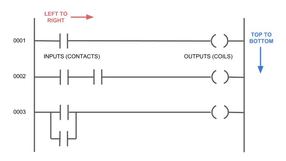
An example of a latch circuit is shown in figure 1.18. — a latch in ladder logic uses one instruction to latch, and a second instruction to unlatch, as shown in figure 1 below. The following illustration is a common “latching circuit” used to turn devices such as motors on and off. However, when there is an output, another set of contacts associated with the output closes. The output with an l inside will turn the output d on when the input a becomes true. once compiled and downloaded to a plc the ladder program is scanned like a book; explain the concept of latching in plc using relevant example. These contacts form an or logic gate system with the input contacts. This guide covers all these. When the input a contacts close, there is an output.
Plc Ladder Diagram Pdf
Latch In Plc Ladder Diagram — a latch in ladder logic uses one instruction to latch, and a second instruction to unlatch, as shown in figure 1 below. — a latch in ladder logic uses one instruction to latch, and a second instruction to unlatch, as shown in figure 1 below. explain the concept of latching in plc using relevant example. — think of ladder logic symbols as the essential pieces of a puzzle in ladder diagrams. However, when there is an output, another set of contacts associated with the output closes. Draw a ladder logic to control a bulb using push buttons in plc with latching. The output with an l inside will turn the output d on when the input a becomes true. once compiled and downloaded to a plc the ladder program is scanned like a book; The following illustration is a common “latching circuit” used to turn devices such as motors on and off. When the input a contacts close, there is an output. These contacts form an or logic gate system with the input contacts. This guide covers all these. An example of a latch circuit is shown in figure 1.18.